CSE 168 Homework 1
OptiX and Acceleration Structure
I implemented OptiX support, which massively reduced render times. Instead of using the provided OptiX 6.5 template, I set it up from scratch with a newer version (OptiX 8.0) and integrated it into my existing submission for CSE 167. However, the ray tracer still uses the CPU backend by default. To enable OptiX, the command backend optix must be included in the scene file. The default is backend cpu.
In my existing CPU implementation, I implemented a Bounding Volume Hierarchy along the lines of Pharr, Jakob, and Humphreys’s description in Physically Based Rendering 4e, alongside an efficient intersection algorithm for axis-aligned bounding volumes given by Ericson’s Real-Time Collision Detection. To disable the BVH, the command accelerator naive must be included in the scene file. The default is accelerator bvh.
A comparison of render times can be found below. The program was compiled with MSVC using /O2 optimization and /openmp paralellization, and it was run on my laptop’s Intel i7-12700H and NVIDIA RTX 3060.
| Scene | CPU w/o BVH | CPU w/ BVH | GPU w/ OptiX |
|---|---|---|---|
| scene4-ambient | 0.053s | 0.037s | 0.003s |
| scene4-diffuse | 0.051s | 0.038s | 0.003s |
| scene4-emission | 0.057s | 0.041s | 0.003s |
| secen4-specular | 0.083s | 0.053s | 0.003s |
| scene5 | 1.879s | 0.050s | 0.004s |
| scene6 | 0.094s | 0.163s | 0.004s |
| scene7 | 93.41s | 0.133s | 0.003s |
| scene8 | N/A | 59.27s | 0.519s |
| scene9 | N/A | 17.09s | 0.143s |
| scene10 | N/A | 104.5s | 0.437s |
Scene render time comparisons between CPU without BVH, CPU with BVH, and GPU with OptiX. Note that scenes 8–10 are too complex to render without acceleration in a reasonable amount of time, so the times are left as N/A. CSE 168 image-grader report.
Using the BVH and OptiX, I was able to render much more computationally taxing scenes (scenes 8–10), such as the one below of a reflective Stanford Dragon in a highly reflective box.
 Scene 9, Stanford Dragon:
 shininess 70 specular .7 .7 .7, 3840x2160
Transmission
I added transmittance and ior (index of refraction) commands. The effect is decently realistic. For example, the following images demonstrate how a transparent sphere warps light at different refractive indices. Notably, a glass ball (ior 1.5) seems to turn the image upside down, which is physically accurate.
As an aside, I would like to note that while my submission in CSE 167 also included transmission, I have since improved upon it by handling total internal reflection. Interestingly, this significantly improved render times in certain cases. Normally, one ray becomes two rays: one reflected and one transmitted. But under total internal reflection, we only need the reflected ray. So one ray becomes one ray, which lessens the exponential explosion.
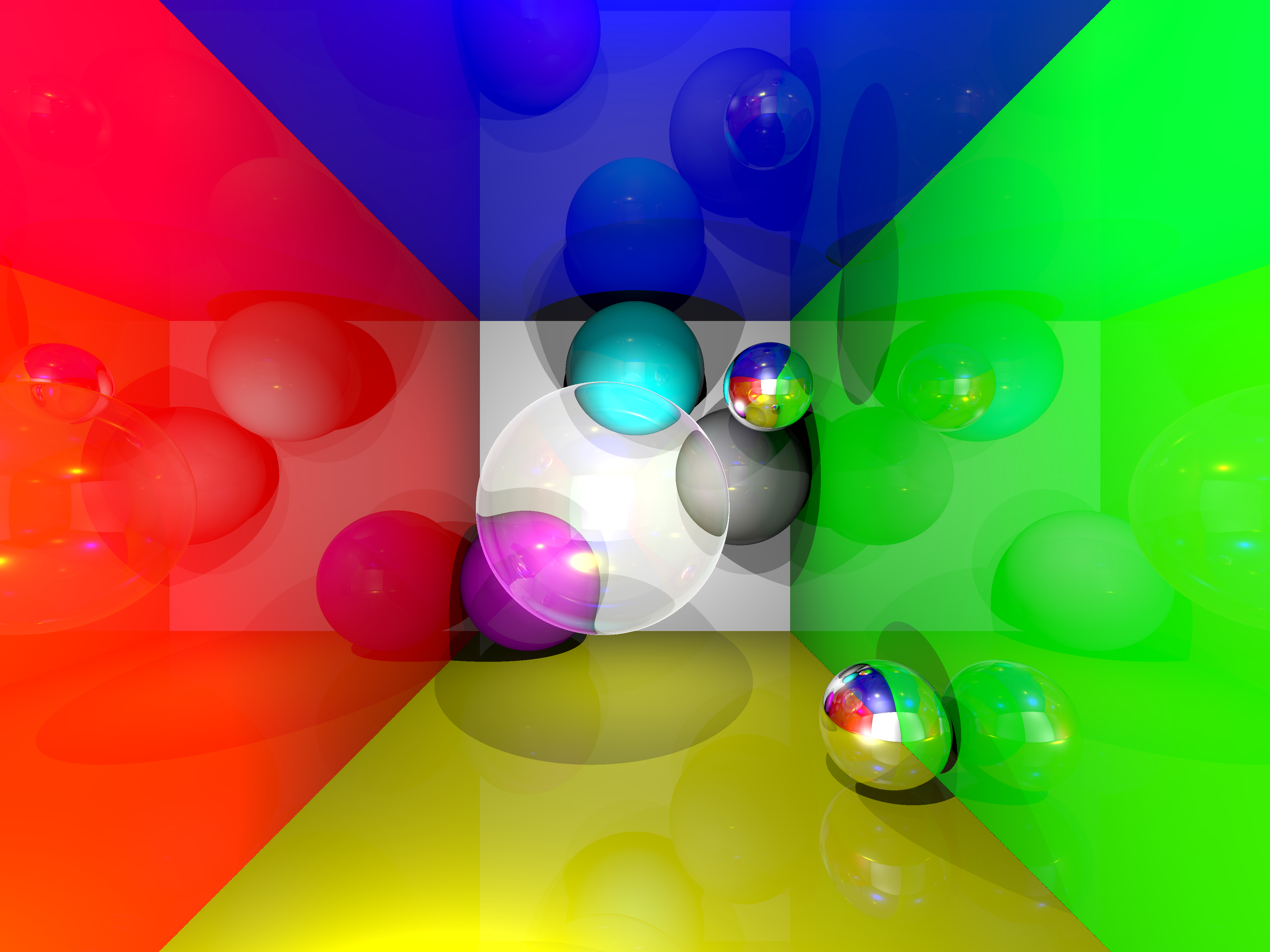 Scene 8, Refractive Sphere:
 ior 1.015, 3840x2880
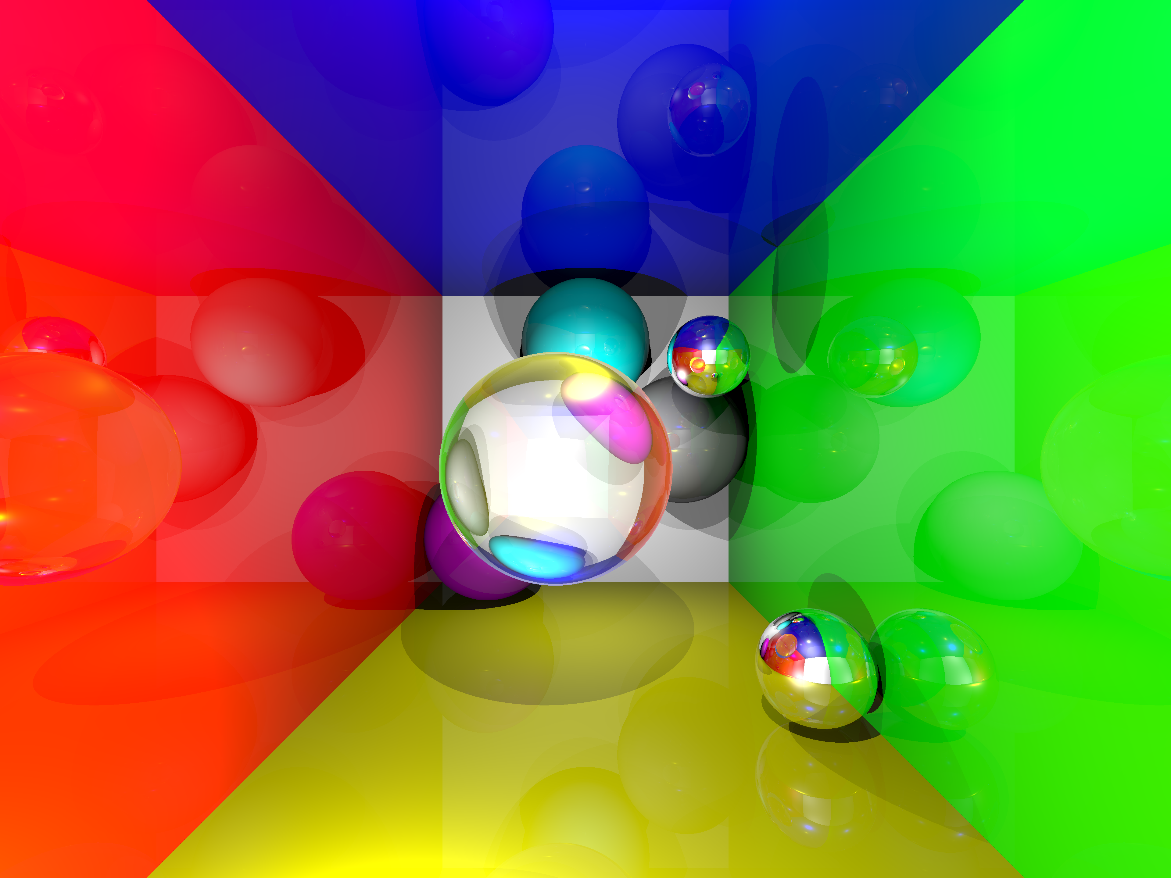 Scene 8, Refractive Sphere:
 ior 1.5, 3840x2880
Just to experiment, I also rendered a few scenes of the Stanford dragon with varying refractive indices and transmittance.
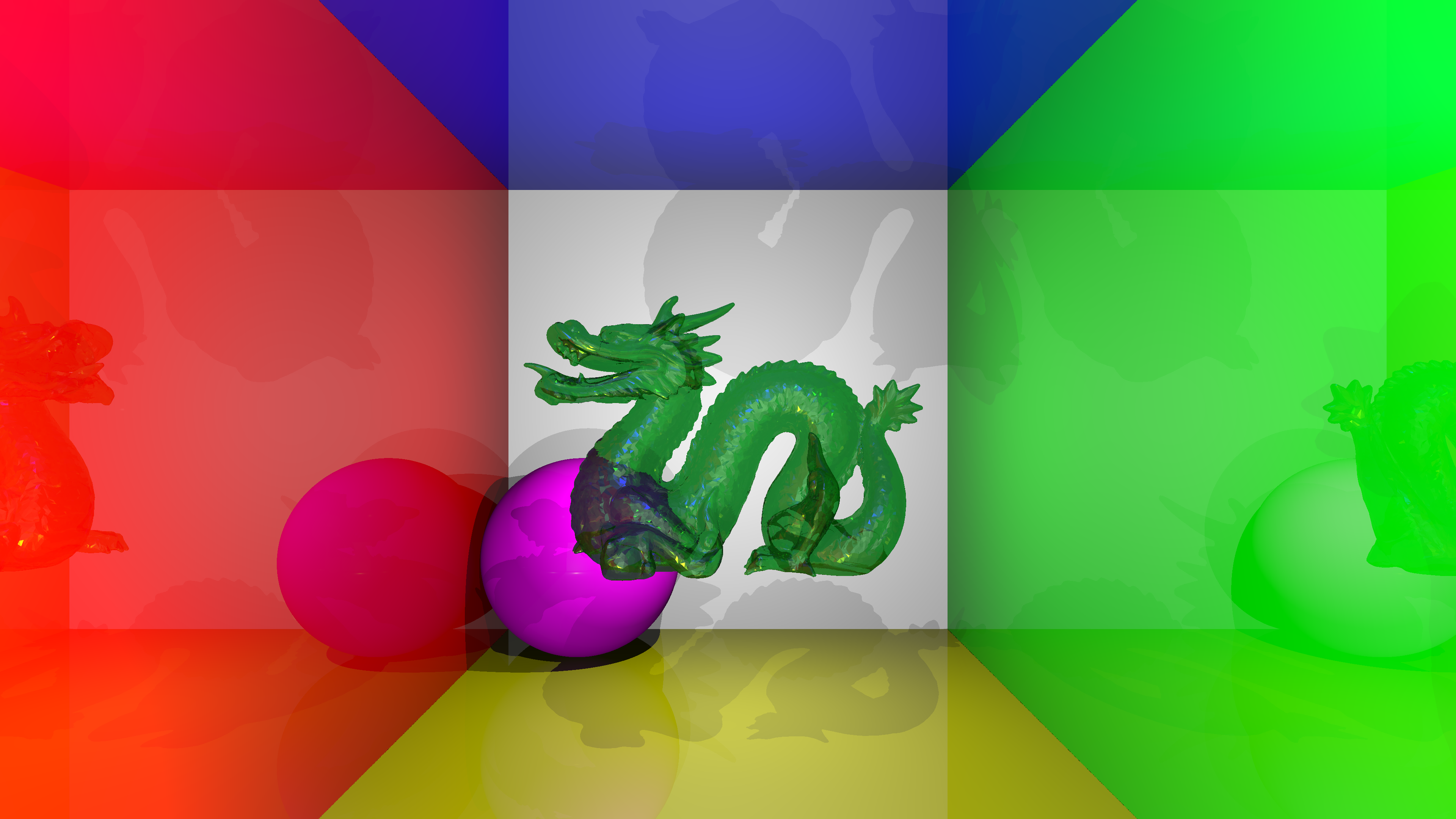 Scene 10, Stanford Dragon:
 ior 1.015 transmittance .37 .74 .47, 3840x2160
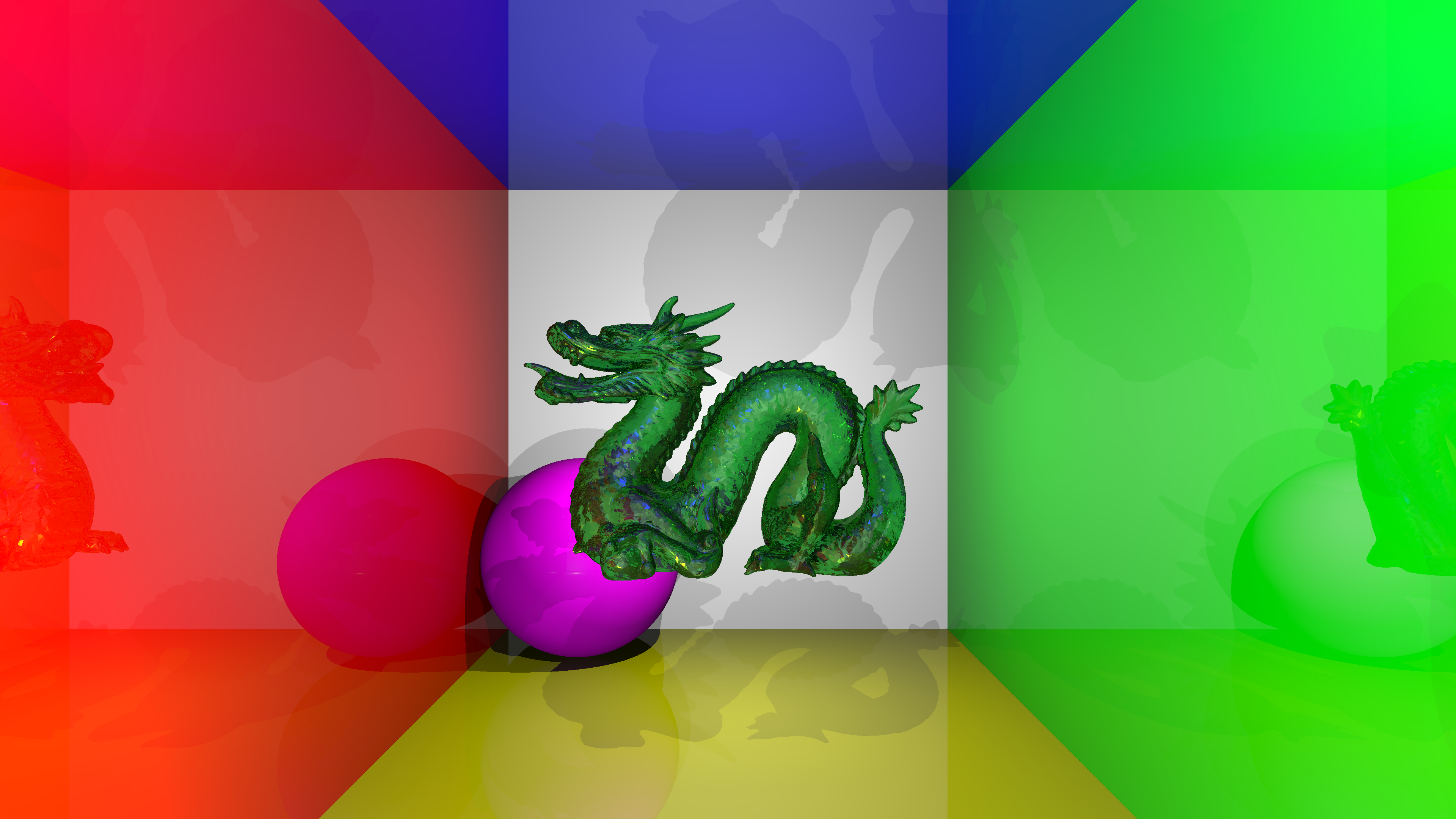 Scene 10, Stanford Dragon:
 ior 1.5 transmittance .37 .74 .47, 3840x2160
![]() Scene 10, Stanford Dragon:
Scene 10, Stanford Dragon: ior 1.5 transmittance .95 .95 .95, 3840x2160
It’s interesting how chaotic/noisy the final image is, as the refractive index is decently high and the model is quite complex/layered. There are also some dark spots near the tail caused by maxdepth being too low, but increasing maxdepth exponentially increases render times. The images above are already rendered with maxdepth 9.
Anti-aliasing
I added a sampler command for scene files with two available options: sampler basic and sampler rgss. With sampler rgss, the program uses Rotated Grid Supersampling (RGSS), which involves shooting 4 rays per pixel in a rotated square, which (loosely) creates a rotated grid. The grid is not perfect, but that could be viewed as a positive. Perfect grids can lead to visual artifacts when certain patterns align with the grid.
All of the images above have been rendered with sampler basic (no anti-aliasing), so below is a comparison between sampler basic and sampler rgss using scene 5. The top half of the renders are excluded because they are simply black.
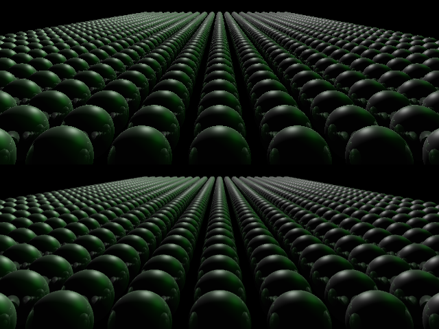 Scene 5:
 sampler basic above, sampler rgss below, 640x480
Gamma Correction
I also added a colorspace command for scene files which allows input/output colors to be in either linear (default) or sRGB. The original assignment required not performing gamma correction. However, PNGs assume sRGB values, which leads to linear outputs looking harsh/wrong. But since the scenes used values based on those linear outputs, simply adding colorspace output srgb without tweaking the values looked quite odd, as shown below. Note that scenes 8–10 were configured with colorspace input srgb and colorspace output srgb.
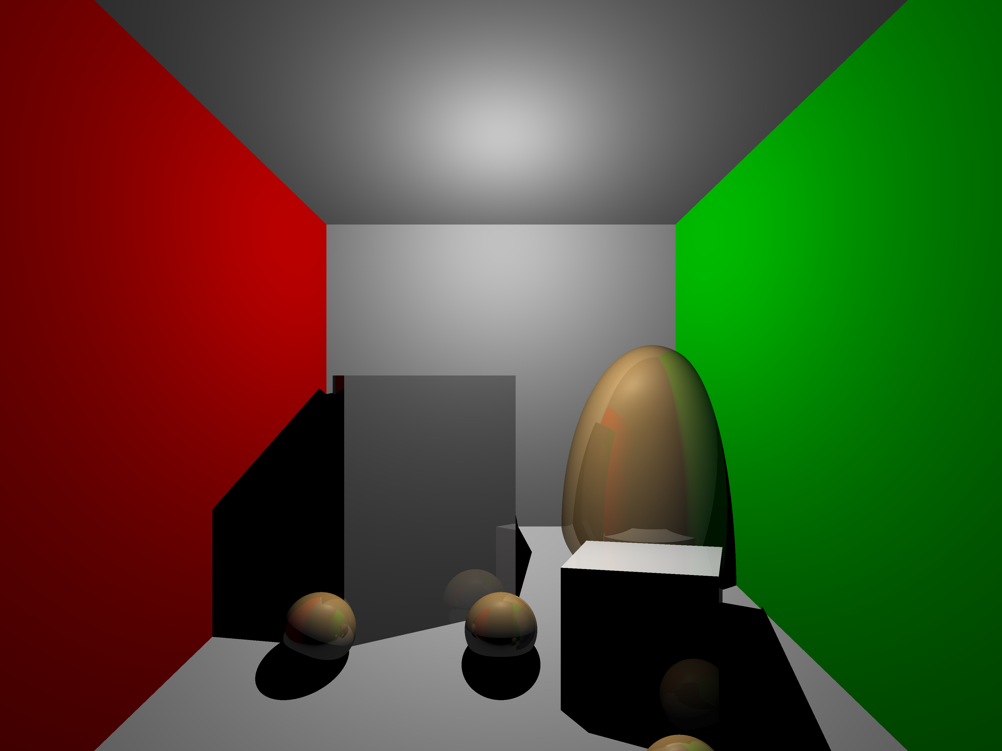 Scene 6:
 colorspace input linear colorspace output linear, 3840x2880
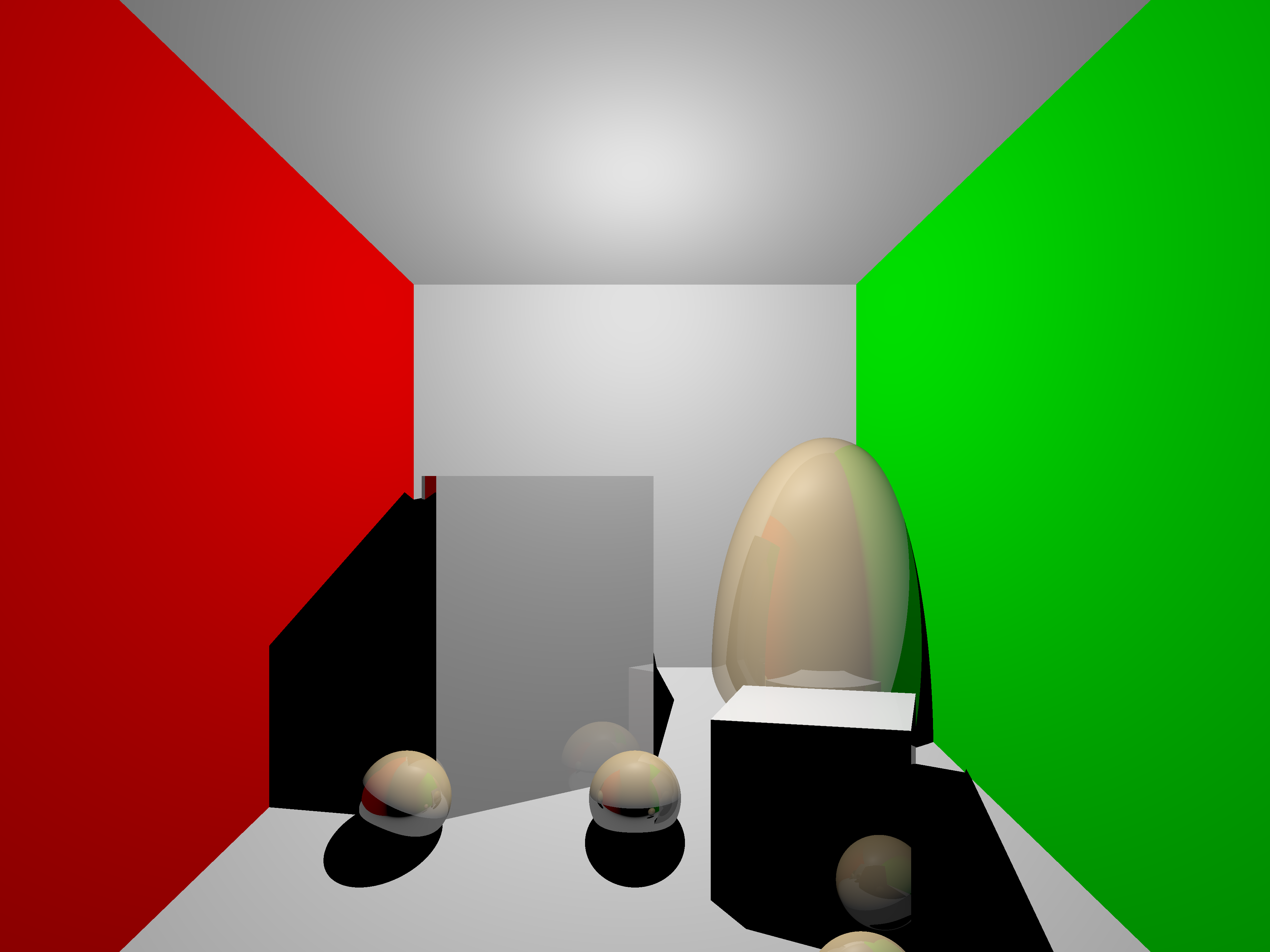 Scene 6:
 colorspace input linear colorspace output srgb, 3840x2880
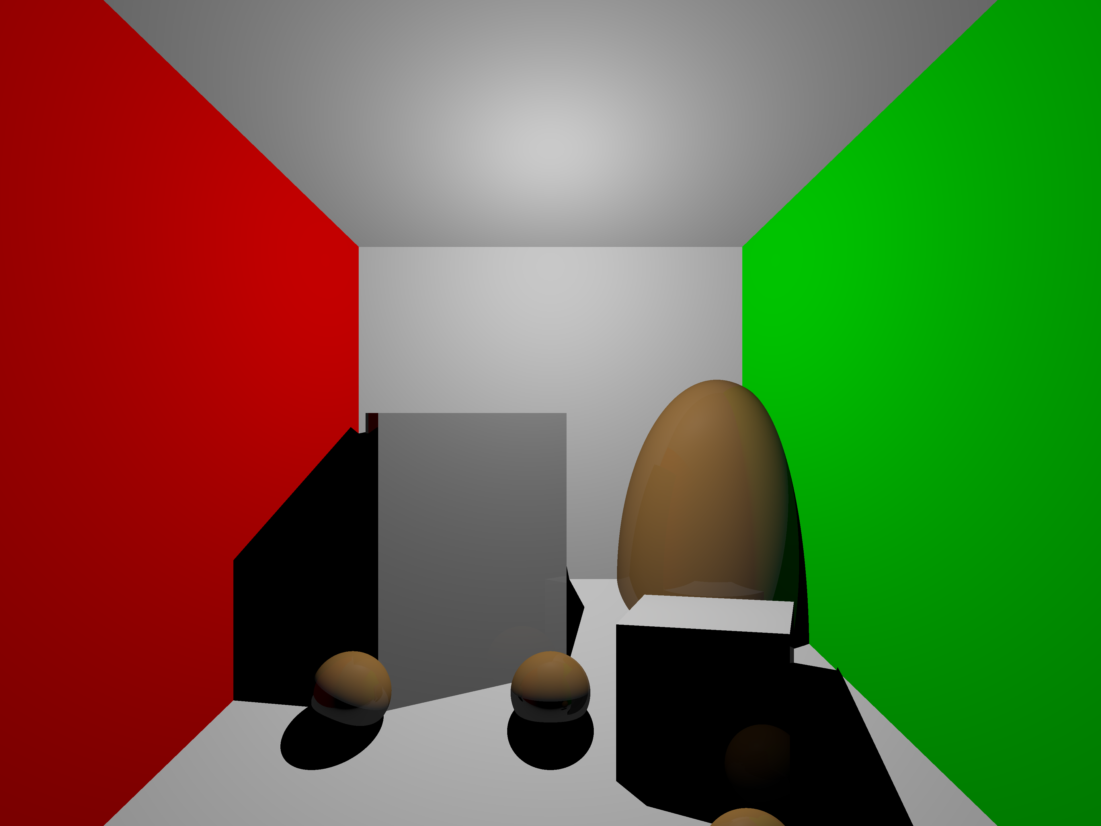 Scene 6:
 colorspace input srgb colorspace output srgb, 3840x2880